Hi Kaitlyn,
Thank you for the clear explanation and diagram!
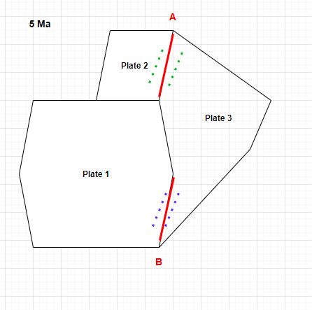
To determine the motion of plate 3 you can pick one of the spreading centres. So you could pick spreading centre A to determine the motion of plate 3 relative to plate 2, and insert only that into the rotation file. Or you could instead pick spreading centre B to determine the motion of plate 3 relative to plate 1. So in the first case (3 relative to 2) you’d have:
001 0.0 0.0 0.0 0.0 000 !Plate 1
001 10.0 0.0 0.0 0.0 000 !
002 0.0 0.0 0.0 0.0 001 !Plate 2
002 10.0 0.0 0.0 0.0 001 !
003 0.0 0.0 0.0 0.0 002 !Plate 3
003 5.0 0.0 0.0 0.0 002 ! Spreading A at 5.0
003 10.0 0.0 0.0 0.0 002 !
…where now you have a single continuous sequence of plate 3 relative to 2 from 0-10Ma (where 3 is the moving plate and 2 is the fixed plate):
003 0.0 0.0 0.0 0.0 002 !Plate 3
003 5.0 0.0 0.0 0.0 002 ! Spreading A at 5.0
003 10.0 0.0 0.0 0.0 002 !
…whereas if you had interleaved that with a different fixed plate ID (ie, 1), as in your example, then you’re starting and stopping rotation sequences (which creates a new set of issues around making sure the two rotation sequences match up at 5Ma, ie, have the same rotation relative to the root plate 0 so that the plates don’t appear to jump when passing through 5Ma, something called crossovers).
As for your two MOR ridge lines, they can be created to reconstruct using half-stage rotations. For example, the 3-relative-2 MOR would be created as…

…and you don’t need to have extra rotations added to the rotation file (the above example just uses existing rotations for plates 3 and 2).
Another point is the motion of plate 1. From the rotation file it looks like you already know the motion of plate 1 (relative to plate 0) so the following probably does not apply to you. However if you only know the motion of plate 1 relative to plate 3 (via spreading centre B) then you can also add that to the rotation file. In this case plate 1 moves relative to plate 3, which itself moves relative to plate 2, which in turns moves relative to plate 0. This means your plate circuit path would be 0 -> 2 -> 3 -> 1. Note that to get the 3 -> 1 part of the circuit the 1 -> 3 rotation gets reversed. In this case you could have something like:
002 0.0 0.0 0.0 0.0 000 !Plate 2
002 10.0 0.0 0.0 0.0 000 !
003 0.0 0.0 0.0 0.0 001 !Plate 3
003 5.0 0.0 0.0 0.0 001 ! Spreading B at 5.0 (plate 3 relative to 1, ie, 1 -> 3)
003 10.0 0.0 0.0 0.0 001 !
003 0.0 0.0 0.0 0.0 002 !Plate 3
003 5.0 0.0 0.0 0.0 002 ! Spreading A at 5.0
003 10.0 0.0 0.0 0.0 002 !
…where I’ve changed plate 2 to move relative to plate 0 (instead of plate 1) just to show the example. Note that there are three 003/001 rows followed by three 003/002 rows (in other words they are not interspersed, and hence avoid the issues mentioned above).
That example looks a bit confusing because it appears plate 3 is moving relative to both plates 1 and 2 over the same 0-10Ma time period (which seems contradictory). But the example should work in this plate circuit scenario (0 -> 2 -> 3 -> 1). Alternatively, it could be written in the more traditional form by reversing the 1 -> 3 rotation to be 3 -> 1:
002 0.0 0.0 0.0 0.0 000 !Plate 2
002 10.0 0.0 0.0 0.0 000 !
001 0.0 0.0 0.0 0.0 003 !Plate 1
001 5.0 0.0 0.0 0.0 003 ! Spreading B at 5.0 (plate 3 -> 1, ie, reverse of 1 -> 3)
001 10.0 0.0 0.0 0.0 003 !
003 0.0 0.0 0.0 0.0 002 !Plate 3
003 5.0 0.0 0.0 0.0 002 ! Spreading A at 5.0
003 10.0 0.0 0.0 0.0 002 !
…and even less confusing is to rename plate 1 to plate 4 so the plate circuit becomes 0 -> 2 -> 3 -> 4:
002 0.0 0.0 0.0 0.0 000 !Plate 2
002 10.0 0.0 0.0 0.0 000 !
003 0.0 0.0 0.0 0.0 002 !Plate 3
003 5.0 0.0 0.0 0.0 002 ! Spreading A at 5.0
003 10.0 0.0 0.0 0.0 002 !
004 0.0 0.0 0.0 0.0 003 !Plate 4
004 5.0 0.0 0.0 0.0 003 ! Spreading B at 5.0
004 10.0 0.0 0.0 0.0 003 !
Although this example is probably not the best advice (since I’m a programmer and have not done any real world modelling of plates), so just putting it there to highlight that different plate circuit approaches can be used depending on the situation.
Regards,
John