Plate boundary display with topologies

Hi all, my colleague and I are working on generating some topologies from plate boundary features, but have noticed some differences in the ways GPlates 2.1 and 2.3 display the boundaries once we load in our topologies. In v2.1 (after loading in our topologies), we are able to see all plate boundary segments, including those that are used to define our topologies. In version 2.3 (and 2.2 as well), we can no longer see topology-defining segments once we’ve loaded in the topologies. We want to be able to tweak our boundary geometries (and therefore our topologies) as we go, but are struggling to do this in version 2.3 as we can’t see them. Our work-around is to eject the topologies from GPlates so that all boundaries are visible, edit the boundary geometries, then re-load the topologies. This process is quite faffy though- is there a better way of doing it? Have we inadvertently done something wrong? Or would the solution be to just stick to version 2.1 for editing purposes? Any advice is very welcome, thanks!

Hi Sheona,

For GPlates 2.2 and 2.3 you can tick this option…

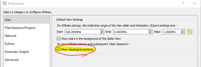
As noted in more detail in this post we changed the default behaviour for novice users (starting with GPlates 2.2) such that they don’t see the dangling bits on topologies (ie, don’t see the plate boundary segments you mention). Advanced users (who actually build/edit topologies) are advised to tick this option so that they’re always visible.

There’s also a small section mentioning this in the user manual here (was added to manual when GPlates 2.3 was released).

Perfect, thanks so much John!