I saw that the new 2.5 updates had teeth on the subduction zones, so I wanted to test that out. However, I can’t figure out how to make them appear. I have been looking around, but I can’t find any documentation where this is described.
I have a feature of type gpml:SubductionZone with some (but not all) fields filled in. I have filled in the plate id (for the overriding plate) and conjugate plate id (for the subducting plate). I had assumed this would be enough, but I guess I have to fill in some specific information or check a box? Change something about the draw style?
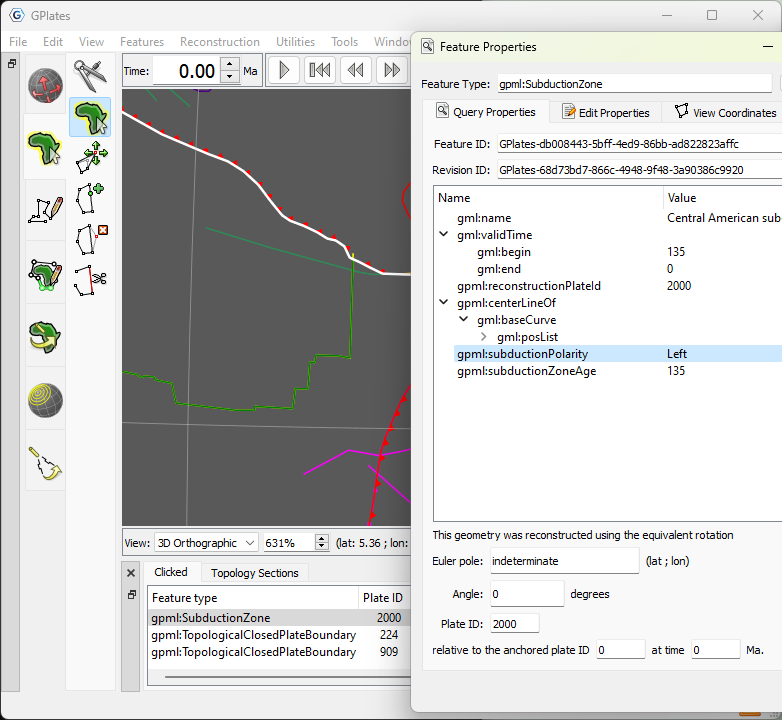
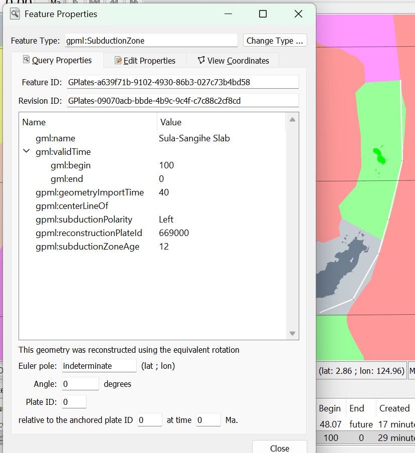
If you look at the geodata that comes with GPlates, the subduction zones have a gpml:subductionPolarity property that indicates which side of the line the overriding plate is on. So you’ll need to add that property to your subduction zones to see the teeth.
For example, in the following screenshot the vertices of the selected line start in the North-West and end in the South-East (you can see this if you hover over the vertices when in Move Vertex tool to see their order). The polarity is Left indicating that the overriding plate is on its left side (which is the upper region in the North-East). And so the teeth point left.
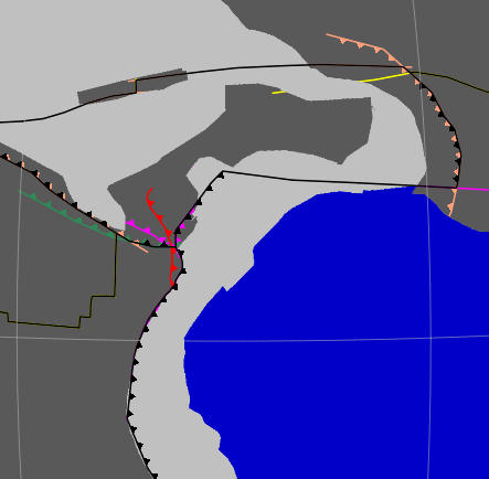
First, I was a bit confused, as I had tried that setting, but after a bit of searching, I found it. The teeth only show if the geometry has been added to a topology. I hadn’t been using topologies yet, but now I’ll see to add them to my workflow.
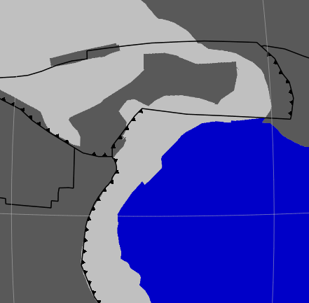
That’s right. And only the part of the subduction line that contributes to a topology’s boundary will have teeth.
Which also means if you hide the topologies that share a particular subduction line (eg, two adjacent plates) then the teeth will also disappear on that particular shared boundary section. By hiding I mean using something like View > Geometry Visibility to hide topologies, or hiding the topology layers.
You can use the same Draw Style for the layer containing the topology as the layer containing the original subduction zone line.
This is because the teeth are rendered/coloured as part of the topological closed plate boundary or topological network (in a purple or brown layer). Whereas the original subduction line is coloured (without teeth) by its layer (usually a green layer, unless it’s a topological line in a purple layer).
Note that you can hide the underlying toothless subduction line (including its dangling bits - that don’t contribute to a topological boundary) using the menu View > Geometry Visibility > Show Topological Sections (this is the default visibility).
As an aside, it’s possible that a subduction line is shared by two adjacent topologies in two different layers. For example, a deforming network (in a brown layer) and a rigid plate (in a purple layer) could share a subduction line between them. In this case, the subduction teeth get coloured twice. Once by the deforming network and once by the rigid plate (which are in different layers with presumably different draw styles). Then whichever layer is on top determines the final visible colour of the teeth.
GPlates 2.5 only works when rendering topological boundaries (ie, topological closed plate boundaries or topological networks).
However here’s a more recent dev build (link valid for 41 days only) that also renders subduction teeth on individual subduction zone features (as covered in this issue). This will be in the next GPlates release.