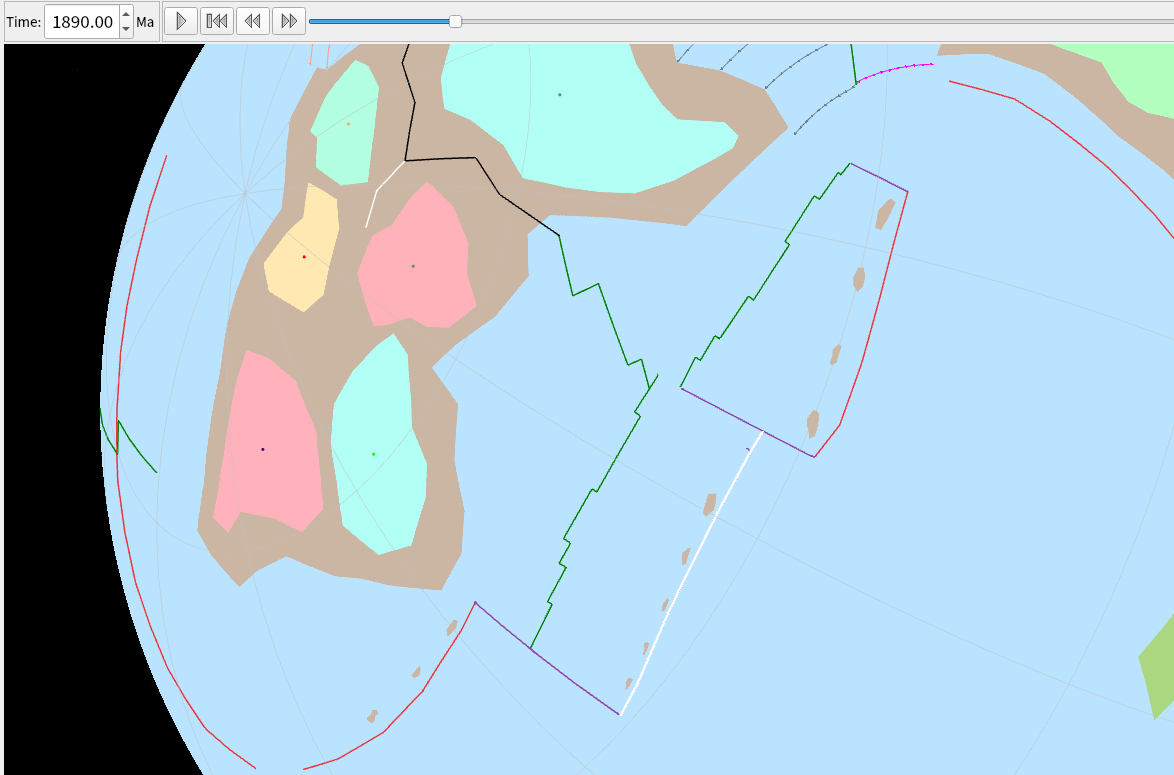
I’ve got two microplates that have pulled away from their parent cratons, and after a certain time these two plates also rift apart. I’m trying to figure out what the rifting zone might look like at the boundary of the microplates, and I think extending the subduction zone of one would be the most logical option for the first 20 Ma or so.
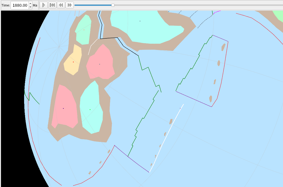
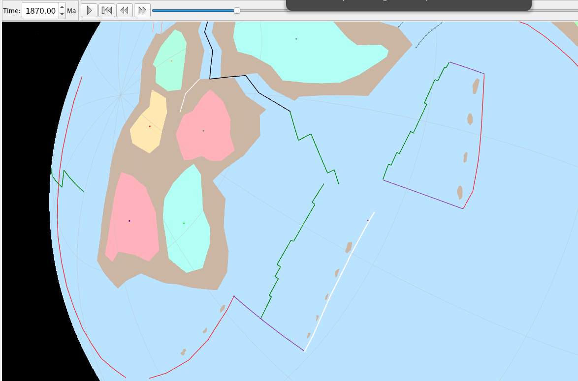
However, I can’t quite figure out how to draw a line topology so that it “extends” because I don’t know where or how to anchor it at the purple transverse boundary. Here’s three screenshots to illustrate what I mean:
I’m not much of a modeller, so I could easily be misunderstanding your scenario, but could you make the white line longer (so that it intersects the purple line for the first 20Ma or so)? The topological boundary, contributed by the white line, will only go up to the intersection point (the dangling bit won’t be included).
It was more that I wanted the subduction zone itself to consist of a topological line, thus allowing me to have an animation similar to Merdith et al (2020), albeit without the symbology on the subduction zone lines. I’m not sure what kind of post-processing they did, as I’ve looked at their GPlates source files and they just use a lot of simple polylines to form topological plate boundaries. I wanted to avoid the post-processing with PyGPlates, as I’ve never had much success getting it to work.
…where I’ve enabled the checkbox View > Geometry Visibility > Show Topological Sections to see the dangling bits (that don’t contribute to the topological plate boundaries).
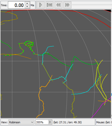
That model does sometimes use a topological polyline when the line needs to deform over time. And then it joins points (that have different plate IDs and so move independently) - you can see the green points in top left of the image. If you wanted something like that then you could anchor some points on one microplate and some on the other (and make your white line a topological line using them) - although I’m not a modeller so I don’t know if that’s good advice.
I thought about it in the time since I posted this, and decided it would be a lot simpler to use regular polylines and overlap them to build topologies later on. It does mean that I will have to figure out how to do postprocessing on exported snapshots later on to indicate what each boundary is (subduction, rift, transverse fault).
It would be nice if there was an option to hide the completed topological boundaries but show their original constituent parts, or something to that effect.