# Calculation of strain rate tensor and Eulerian strain
**URL:** https://discourse.gplates.org/t/calculation-of-strain-rate-tensor-and-eulerian-strain/593
**Category:** Q&A
**Created:** [9 November 2022 14:34 UTC](https://discourse.gplates.org/t/calculation-of-strain-rate-tensor-and-eulerian-strain/593 "2022-11-09T14:34:05Z")
**Posts on this page:** 4
**Page:** 1
### Author:  [@thomas.schouten](https://discourse.gplates.org/u/thomas.schouten)
#### Post date: [9 November 2022 14:34 UTC](https://discourse.gplates.org/t/calculation-of-strain-rate-tensor-and-eulerian-strain/593/1 "2022-11-09T14:34:05Z")
Hi,
GPlates allows the user to retrieve the deformation field and a number of scalar values describing strain for deforming networks. My understanding of the algorithm behind this is the following:
Firstly, it seems the strain rate is calculated for a triangular element. The triangulation of the mesh is updated at every timestep. For advecting Lagrangian markers, their location in the next time step (whether forward or backward in time) is then calculated using the relative coordinates in the triangular element (i.e. a shape function in for finite element methods).
My questions are the following:
1. I can generate a velocity field on a set of Eulerian points for any reference frame. Are these velocities calculated by simply using the vector distance between the current and projected location of these Eulerian points in the adjacent timesteps (depending on the choice of T, T+dt, T-dt, T or T-1/2dt, T+1/2dt as time interval for which the velocity is determined) divided by the time interval dt?
2. GPlates exports information on strain as a scalar value attached to a Lagrangian marker. This means means that the obtained strain fields is asymmetric in time, i.e when going from 100 to 0 Ma or from 0 to 100 Ma, I obtain two different sets of strain fields. In my reconstruction, this leads to either large gaps or between markers (going backwards in time) or a huge pile of markers in one place (going forward in time). Eulerian fields on the other hand are in principle symmetric in time. Is it also possible to export the strain fields for a set of Eulerian points?
Many thanks!
Thomas
---
### Author:  [@john.cannon](https://discourse.gplates.org/u/john.cannon)
#### Post date: [15 November 2022 09:22 UTC](https://discourse.gplates.org/t/calculation-of-strain-rate-tensor-and-eulerian-strain/593/2 "2022-11-15T09:22:29Z")
Hi Thomas,
For some GPlates background related to this functionality, take a look at:
- The section _Software elements for Deforming Topological Networks_ in [Global Tectonic Reconstructions with Continuously Evolving Deforming and Rigid Plates](https://doi.org/10.1016/j.cageo.2018.04.007).
- Figure 1 of [A global plate model including lithospheric deformation along major rifts and orogens since the Triassic](https://doi.org/10.1029/2018TC005462)
> [@thomas.schouten](#):
>
> Firstly, it seems the strain rate is calculated for a triangular element.
Yes, however there are options to smooth the strain rate to avoid the triangular faceted nature of strain rate…
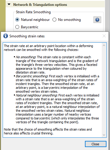
> [@thomas.schouten](#):
>
> The triangulation of the mesh is updated at every timestep. For advecting Lagrangian markers, their location in the next time step (whether forward or backward in time) is then calculated using the relative coordinates in the triangular element (i.e. a shape function in for finite element methods).
Essentially yes, that applies when barycentric interpolation is used, since coordinates are relative to the triangle (containing the marker point) only.
In GPlates, there’s a choice between barycentric and natural neighbour interpolation. The latter is where interpolation include vertices from nearby triangles also (to help reduce the faceted effect of the triangulation on reconstructed/deformed point positions).
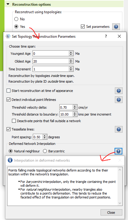
But note that, in pyGPlates, only natural neighbour interpolation is supported since this gives better results (barycentric interpolation is still available in GPlates for legacy reasons however). For example, in [this sample code that reconstructs points using topologies](https://www.gplates.org/docs/pygplates/sample-code/pygplates_reconstruct_crustal_thickness_and_tectonic_subsidence.html) it will always use natural neighbour interpolation for any points within deforming networks.
> [@thomas.schouten](#):
>
> I can generate a velocity field on a set of Eulerian points for any reference frame. Are these velocities calculated by simply using the vector distance between the current and projected location of these Eulerian points in the adjacent timesteps …
By Eulerian points I’m assuming you mean points that don’t move relative to a reference frame (such as the classical case of calculating velocities at points with plate ID zero, or anchor plate ID). Inside deforming networks this is actually similar to reconstructing/deforming the point locations - in that it will calculate the velocities at the neighbouring triangulation vertices and interpolate them using natural neighbour interpolation (barycentric is not an option here). And actually it doesn’t matter if the points themselves move or not (static or reconstructed), so it works for the Lagrangian markers also.
And the velocity at each triangulation vertex is calculated using the vertex position and its stage rotation (based on its plate ID).
> [@thomas.schouten](#):
>
> Is it also possible to export the strain fields for a set of Eulerian points?
If I understand correctly then I don’t think this is possible. The exporting of strain fields is based on reconstructed/deforming points (Lagrangian). Mostly this is a result of accumulating total strain over the lifetime of a reconstructed/deformed point (whereas strain _rate_ is an instantaneous quantity, ie, no accumulation).
> [@thomas.schouten](#):
>
> This means means that the obtained strain fields is asymmetric in time, i.e when going from 100 to 0 Ma or from 0 to 100 Ma, I obtain two different sets of strain fields.
The reconstructed/deformed positions are reversible (symmetric in time), and also the crustal thinning equations have been implemented to ensure they’re reversible (in the sense that you could start at 0Ma and solve backward in time to 100Ma and then solve forward in time to 0Ma and you’d end up with the same crustal thickness you started with). So I think the strain rate would be reversible too (but not entirely sure).
> [@thomas.schouten](#):
>
> In my reconstruction, this leads to either large gaps or between markers (going backwards in time) or a huge pile of markers in one place (going forward in time).
How are you reconstructing using the strain fields? I’m a little surprised there seems to be such a large asymmetry.
---
### Author:  [@thomas.schouten](https://discourse.gplates.org/u/thomas.schouten)
#### Post date: [15 November 2022 12:50 UTC](https://discourse.gplates.org/t/calculation-of-strain-rate-tensor-and-eulerian-strain/593/3 "2022-11-15T12:50:27Z")
Hi John,
Thanks a lot for your answer!
> By Eulerian points I’m assuming you mean points that don’t move relative to a reference frame (such as the classical case of calculating velocities at points with plate ID zero, or anchor plate ID). Inside deforming networks this is actually similar to reconstructing/deforming the point locations - in that it will calculate the velocities at the neighbouring triangulation vertices and interpolate them using natural neighbour interpolation (barycentric is not an option here). And actually it doesn’t matter if the points themselves move or not (static or reconstructed), so it works for the Lagrangian markers also.
Yes, that is exactly what I am trying to do. I have a plate (Eurasia) and a deforming plate boundary (Tibetan-Himalayan orogen) at its margin, and I would like to quantify the strain (rate) field from my reconstruction of that area.
> The reconstructed/deformed positions are reversible (symmetric in time), and also the crustal thinning equations have been implemented to ensure they’re reversible (in the sense that you could start at 0Ma and solve backward in time to 100Ma and then solve forward in time to 0Ma and you’d end up with the same crustal thickness you started with). So I think the strain rate would be reversible too (but not entirely sure).
Well, if I create deforming mesh points with a particular density level (say 0.1 degrees) at 100 Ma and solve forward in time to 0 Ma, I get areas where markers get bundled up: this is a problem especially at corners of region of strike-slip motion. Furthemore, in areas where I try to model vertical axis rotations, I had to resort to using semirigid blocks within the deforming mesh to force GPlates to advect the markers with that rotation. Because of coeval shortening, I obtain gaps between the blocks when going from 0 to 100 Ma. When going forward, this means that some markers will have infinite contraction at 0 Ma if at 100 Ma they plot in the gap.
Starting with markers distributed at 0.1 degrees and advecting them back in time creates the opposite problem: markers are bundled up in corners of strike-slip areas (but now in the other corner) and I obtain gaps with no markers between my rotating semirigid blocks at 100 Ma.
That means that while the strain rate is indeed symmetric if I go from 0 to 100 back to 0 Ma, it is dependent on the time at which I define my markers. Eulerian points would not have this problem, as they would follow the calculation of the velocity at those unmoving points. I understand the reasoning for using Lagrangian markers that allow you to track the strain history of each individual marker, but I was wondering if both options would be available.
Cheers,
Thomas
---
### Author:  [@john.cannon](https://discourse.gplates.org/u/john.cannon)
#### Post date: [24 November 2022 04:12 UTC](https://discourse.gplates.org/t/calculation-of-strain-rate-tensor-and-eulerian-strain/593/4 "2022-11-24T04:12:39Z")
Hi Thomas,
Ah I think I understand what you mean now. So the _“strain fields is asymmetric in time”_ and the _“strain rate is indeed symmetric”_ are both true (and not contradictory) because the _strain fields_ are currently calculated at moving (Lagrangian) points and the _strain rate_ is something you might think of in terms of fixed locations (Eulerian).
(As a quick aside, by _strain fields_ I’m assuming you mean _strain **rate** fields_ since _strain_ is an accumulated quantity with a history attached to a specific moving point, ie, Lagrangian. And so you would like to have the option of a Eulerian strain **rate** field, rather than Eulerian strain field).
So the bunching up of Lagrangian points is actually just a natural result of deformation compression/expansion. In other words, as you noted with _“it is dependent on the time at which I define my markers”_, if you have a bunch of uniformly spaced Lagrangian points at 100Ma they will no longer have uniform spacing at 0Ma (and, conversely, uniform Lagrangian points at 0Ma won’t be uniformly spaced when reconstructed back to 100Ma). So that’s the asymmetry you’re referring to. And, as you say, Eulerian points would not have this problem.
So yes, it makes sense to have the ability to calculate strain rates at both fixed and moving points (at which velocities are currently calculated). Currently for strain rates it’s just at moving points, but the functionality could be made available to pyGPlates initially (and then ultimately GPlates).
Currently pyGPlates exposes Lagrangian points via [pygplates.TopologicalModel.reconstruct\_geometry](https://www.gplates.org/docs/pygplates/generated/pygplates.topologicalmodel#pygplates.TopologicalModel.reconstruct_geometry) (see [this sample code](https://www.gplates.org/docs/pygplates/sample-code/pygplates_reconstruct_crustal_thickness_and_tectonic_subsidence.html)). However, while that exposes crustal thinning and tectonic subsidence, it does not yet expose strain rate or accumulated strain (or velocity for that matter). So I’ll add those for the next release. For Eulerian points, on the other hand, I’ll aim to add something similar to velocities (but only strain rate, not accumulated strain). And velocities themselves will also be improved since the current way to calculating velocities ([here](https://www.gplates.org/docs/pygplates/sample-code/pygplates_calculate_velocities_by_plate_id.html) and [here](https://www.gplates.org/docs/pygplates/sample-code/pygplates_calculate_velocities_in_dynamic_plates.html)) is a bit too low level, and currently doesn’t include deforming networks.